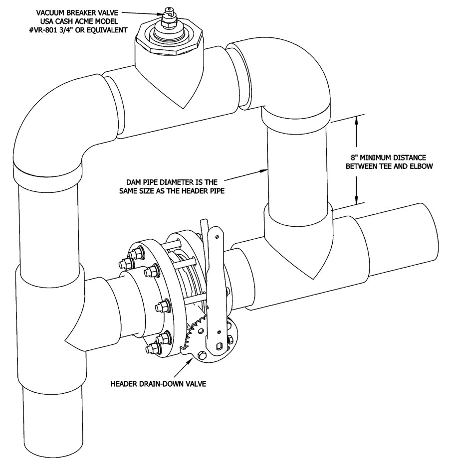
Typical Vacuum Breaker / Anti-Siphon System
X


(Open)

(Open)
- Installation Notes
- The purpose of the vacuum breaker / anti-siphon system (also called a drain back dam) is to retain water in the header system during shut down and to eliminate air purge and shock to plumbing during start up.
- It is necessary to duplicate this arrangement on both the supply and return lines.
- The drain-down valve allows header draining for system maintenance and is closed during normal operation.
- The vacuum breaker must be located a the highest point in the system nearest to the tank to be most effective. A nipple length of 8 inches minimum is required to create sufficient vacuum to open the Cash Acme breaker valve.
- This drawing is supplied to demonstrate a possible piping configuration for the equipment and is general in nature showing pipe sizes and basic routing>
- It is not intended to be inclusive of every detail required for specific location and installation.
- Consult with a professional engineer to determine specific needs before installation.
Need Application Assistance?
Our Experienced Team Can Save You Time & Money.
Tell Us About Your Project


